
Sample Zoning Layouts.
|
Systemzone and Systemlex make it simple to configure heating zones with a variety of heating sources and heat emitters. The following examples illustrate what can be achieved using the unique features of Systemlink zoning products. For more technical information on a greater number of the more frequently encountered layouts, please refer to the Schematics Database.
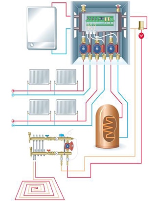
Domestic installation - larger house This diagram shows the Systemlink unit in a domestic setting. The Systemlink unit consists of a Systemzone and Systemlex in an enclosure with pumps, valves and automatic air vent. There is one boiler serving four heating zones:
|
|
|
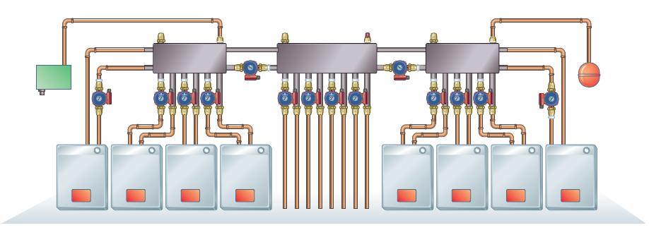
Boiler arrays - for commercial and industrial applications
SystemZone makes it very easy to install and operate multiple boilers The two outside Systemzones are fed by the heat sources. As these operate independently of each other, any combination of boilers can be used to match the load to the optimum operating level of the boilers. Heat sources can be taken off line for maintenance or replacement without interrupting service. The central Systemzone takes the output from the heat sources and delivers it to the heating zones - four in this example. These can be further subdivided into additional zones by using more Systemzones. Using multiple boilers rather than one or two large ones can greatly reduce the initial capital cost. For instance, using balanced flue boilers can save the expense of a high chimney. |
|
|
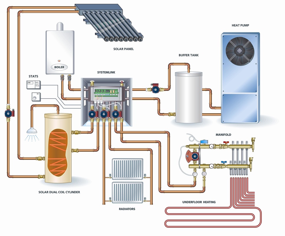
Renewable energy configuration
The schematic to the right shows a typical configuration where Systemzone and Systemlex are used to integrate all the elements:
|
|