
FAQ.
Systemlink answers many technical questions every day. We list below some of those most frequently asked.Please click on a question below to see the answer.
|
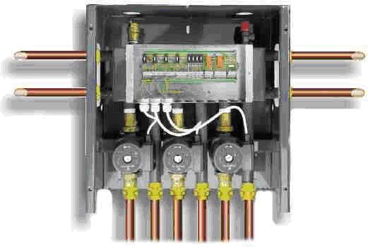
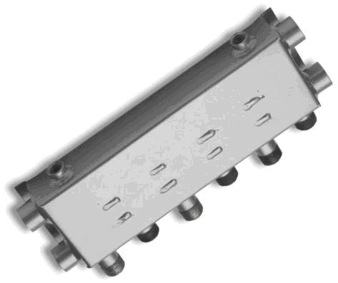
There are two basic products to choose from: the SystemLink Zoning Centre or the SystemZone manifold. The SystemLink Zoning Centre contains the SystemZone manifold and SystemLex wiring centre mounted in a cabinet with pumps already attached and prewired, plus automatic air vent and safety valve. The SystemLink Zoning Centre is sold with 1-inch connections only; however the SystemZone manifold is sold in a variety of sizes with connections up to 2-inches.
|
|
|
To choose the correct manifold, two basic questions must first be answered:
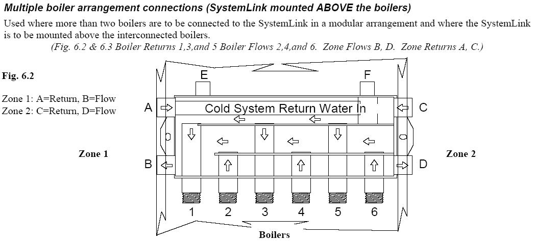
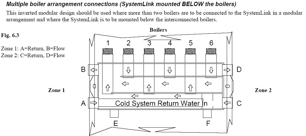
If more than 6 flow/return pairs are required, two manifolds can be linked to provide the extra capacity. For example, if 7 pairs are required, a SystemZone 5 and a SystemZone 4 may be linked to provide this. However, because of the built-in bypass, a pump is necessary between the two manifolds to provide circulation.
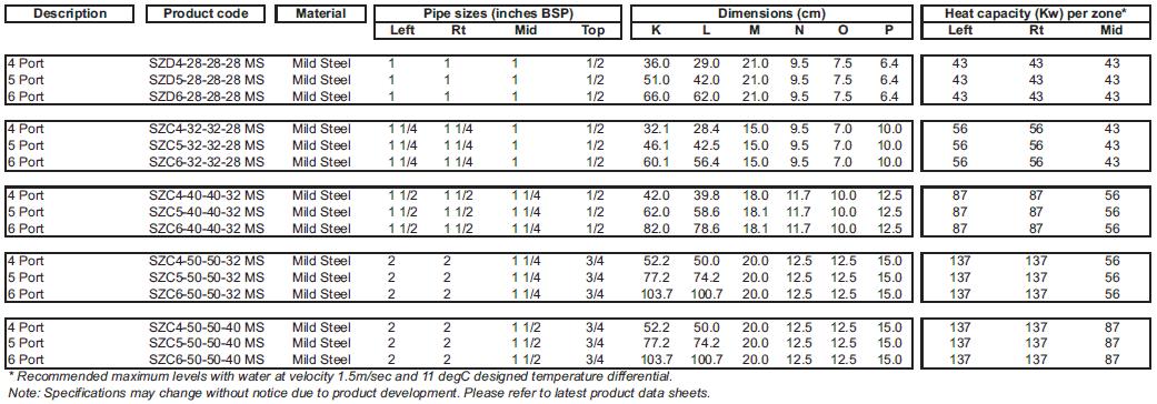
Choose appropriately sized connections on the manifold based on the table below, which shows the rated heat capacity per zone in kW for various connection sizes:
Choose appropriately sized connections on the manifold based on the table below, which shows the rated heat capacity per zone in kW for various connection sizes:
- How many heat sources?
- How many zones? (Include both heating and domestic hot water.)
If more than 6 flow/return pairs are required, two manifolds can be linked to provide the extra capacity. For example, if 7 pairs are required, a SystemZone 5 and a SystemZone 4 may be linked to provide this. However, because of the built-in bypass, a pump is necessary between the two manifolds to provide circulation.
Choose appropriately sized connections on the manifold based on the table below, which shows the rated heat capacity per zone in kW for various connection sizes:
Choose appropriately sized connections on the manifold based on the table below, which shows the rated heat capacity per zone in kW for various connection sizes:
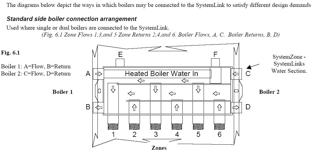
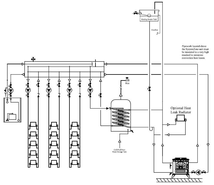
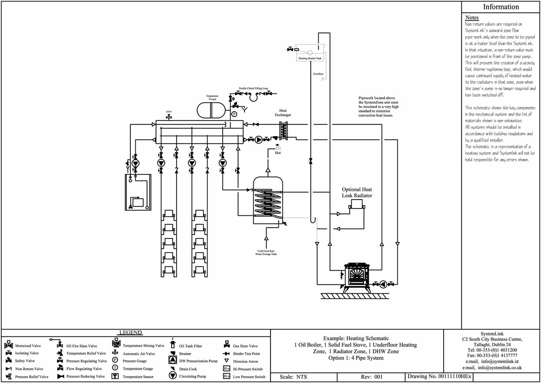
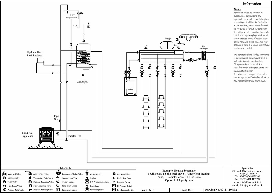
The SystemLink manifold may be used to interconnect solid fuel boilers to oil or gas boiler systems as illustrated below.
The diagrams below show two common solid fuel configurations:
Schematic of a four-pipe solid fuel system:
The diagrams below show two common solid fuel configurations:
- Four-pipe system
- Two-pipe system
Schematic of a four-pipe solid fuel system:
Schematic of a two-pipe solid fuel system:
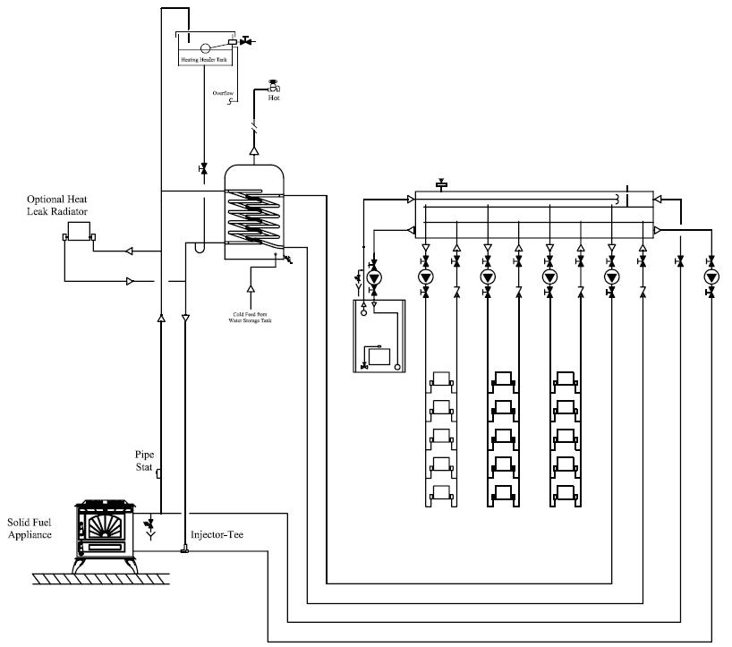
The SystemLink manifold may be used to interconnect solid fuel boilers to oil or gas boiler systems as illustrated below. It is very similar to an open-vented only system but you must install a Plate Heat Exchanger between the manifold and the solid fuel heat source
The diagrams below show two common solid fuel configurations:
Schematic of a four-pipe solid fuel system:
The diagrams below show two common solid fuel configurations:
- Four-pipe system
- Two-pipe system
Schematic of a four-pipe solid fuel system:
Schematic of a two-pipe solid fuel system:
It’s important to note that a SystemLex rather than a MiniLex should be used to control this system. Please consult theSchematics Database for wiring diagrams appropriate for your layout.
